IPv6-based Wi-Fi Hotspots
Apple’s 2015 WWDC event included a great session on IPv6 & TCP changes coming with iOS 9. There is a related post to the IETF v6ops mailing list here. The new IPv6 hotspot is very interesting to me. These are my notes on how hotspot functionality can work with IPv6, and no NAT.
IPv4 Hotspot - (aka the simplicity of NAT?)
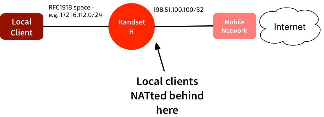
The current IPv4 hotspots use simple NAT, similar to most home network setups. The mobile network assigns a public IPv4 /32 address to the handset, H. The handset picks a local RFC1918 address space for its connectivity to local clients, and hands that out via DHCP. Hide NAT is used to provide outbound internet connectivity for those clients.
What about IPv6? Isn’t NAT verboten?
NAT is evil, right? We can’t use NAT to hide the local clients behind the handset. So how do we provide IPv6 hotspot functionality? One way would be to use DHCPv6 PD. When the hotspot is enabled, the mobile device could request a prefix via DHCPv6 PD. That could then be used for local devices.
Unfortunately the mobile networks don’t do DHCPv6 PD yet. It’s not clear if they will do any time soon either. We need an interim measure.
There’s a couple of options, and they both exploit the fact that handsets are allocated a /64 prefix, rather than a /128 (i.e. the equivalent of an IPv4 /32). Apple has announced support for a variant of one of these options in iOS 9.
Background: IPv4 Proxy ARP
A quick refresher on Proxy ARP:
Proxy ARP is the technique in which one host, usually a router, answers ARP requests intended for another machine. By “faking” its identity, the router accepts responsibility for routing packets to the “real” destination.
In the network below, A & B have the wrong subnet masks. Normally they should not be able to communicate. But if router P is running proxy ARP, it will ‘fake’ ARP responses from each router. A & B will think they’re communicating directly across the same broadcast domain, even though it’s P relaying the traffic.
Note that this is different behaviour to a simple bridge, which just forwards frames without changing them.
RFC 7278: Extending an IPv6 /64 Prefix from a 3GPP Mobile Interface to a LAN Link
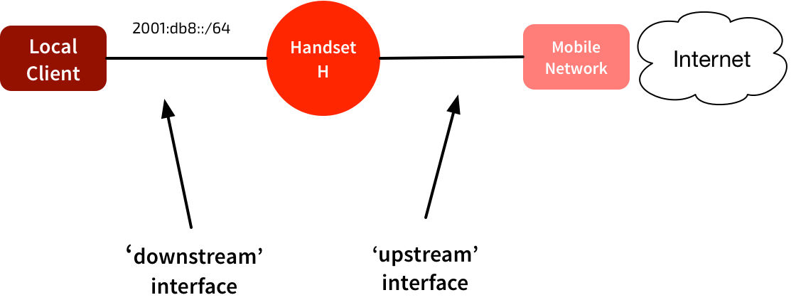
A normal connection looks like this:
Note that a /64 is assigned to handset. It chooses an address from that /64, and the mobile network routes traffic to that /64 to the handset.
To work as a hotspot, the /64 is moves from the ‘upstream’ network to the ‘downstream’ network. The handset can keep the same address. It sends out RAs, and devices using the hotspot will automatically address themselves in that same /64. The GGSN/PGW still routes all traffic addressed to that /64 to the handset. The handset will process any locally-destined traffic, and forward traffic to other addresses in the /64.
This method is quite elegant. It exploits two things:
-
The GGSN/PGW connection to the handset acts like a P2P interface. No Neighbor Discovery is performed - it just forwards all traffic routed to the /64 directly to the handset.
-
The GGSN/PGW does not use any address on the allocated /64. So there’s no concern about a local device attempting to use the same address as the PGW.
If the PGW had assigned a /128, this wouldn’t work. But because it’s a /64, we can easily assign other addresses from the same prefix. The PGW doesn’t seem to care that it sees more than one IPv6 address. As long as they’re all in the same /64, it works. No need to proxy any RA or ND messages.
It does have limitations - it only works when the upstream connection is effectively a point-to-point network, and won’t work if there are loops or multiple routers.
RFC 4389: Neighbor Discovery Proxies
This technique is closer to the proxy ARP model. It is a more complicated technique, but one that works in a wider variety of networks.
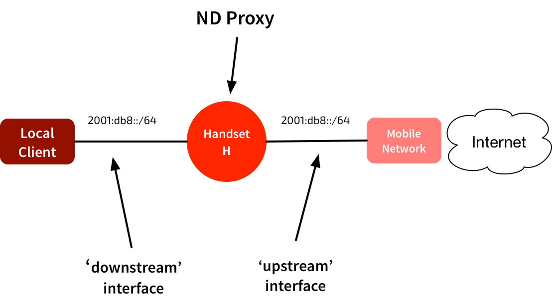
Again, the mobile network has assigned a /64 to the handset. But rather than ‘moving’ that /64 to the downstream network, in this model the handset squats in the middle of the network.
In this network there could be hosts in that same /64 on both the ‘upstream’ and ‘downstream’ side of the handset. To glue this together, the device in the middle proxies IPv6 Neighbor Discovery packets. These are the approximate equivalent of ARP in an IPv4 network.
When the upstream router sends out a Route Advertisement packet, the handset uses that to configure its own addressing & routing. It then forwards the RA out the downstream interface, so any connected devices can auto-configure their own addresses & routing.
The handset in the middle puts its interfaces into “all-multicast” mode. It maintains a neighbor cache for both interfaces. It checks received IPv6 packets to see if they need to be handled locally, forwarded unchanged (apart from new link-layer addresses) or proxied. It proxies anything that negotiates link-layer addresses - I.e. NS, NA, RA, & ICMPv6 redirects.
Those packets contain link-layer addresses both in the link-layer header & in the payload. Both of these need to be modified. It works in a very similar way to proxy ARP, tricking systems into forwarding frames via a different system. If you modify the NS/NA/RA packets, you’ll end up with all unicast traffic being forwarded to your link-layer address.
The example in the RFC is pretty good:
Consider the following topology, where A and B are nodes on separate segments which are connected by a proxy P:
A—|—P—|—B a p1 p2 b
A and B have link-layer addresses a and b, respectively. P has link-layer addresses p1 and p2 on the two segments. We now walk through the actions that happen when A attempts to send an initial IPv6 packet to B.
A first does a route lookup on the destination address B. This matches the on-link subnet prefix, and a destination cache entry is created as well as a neighbor cache entry in the INCOMPLETE state. Before the packet can be sent, A needs to resolve B’s link-layer address and sends a Neighbor Solicitation (NS) to the solicited-node multicast address for B. The Source Link-Layer Address (SLLA) option in the solicitation contains A’s link-layer address.
P receives the solicitation (since it is receiving all link-layer multicast packets) and processes it as it would any multicast packet by forwarding it out to other segments on the link. However, before actually sending the packet, it determines if the packet being sent is one that requires proxying. Since it is an NS, it creates a neighbor entry for A on interface 1 and records its link-layer address. It also creates a neighbor entry for B (on an arbitrary proxy interface) in the INCOMPLETE state. Since the packet is multicast, P then needs to proxy the NS out all other proxy interfaces on the subnet. Before sending the packet out interface 2, it replaces the link-layer address in the SLLA option with its own link-layer address, p2.
B receives this NS, processing it as usual. Hence it creates a neighbor entry for A mapping it to the link-layer address p2. It responds with a Neighbor Advertisement (NA) sent to A containing B’s link-layer address b. The NA is sent using A’s neighbor entry, i.e., to the link-layer address p2.
All reasonably straightforward. Yes?
Apple’s Version
Apple has implemented something similar to this in iOS 9. The source code is here. They have ‘scoped’ and ‘non-scoped’ interfaces. ‘Non-scoped’ are the regular ‘global’ interfaces we’re used to. They’re the ‘upstream’ interfaces in the diagrams above. When an interface is marked for proxying, non-scoped on-link prefixes are shared with other ‘scoped’ interfaces.
From my reading, it all looks very similar to RFC 4389. It looks like it inspects the ND packets a little more closely, and only proxies them if they’re for a global prefix obtained from an RA. But note this comment in the source code:
Note that this is not a strict implementation of RFC 4389, but rather a derivative based on similar concept. In particular, we only proxy NS and NA packets; RA packets are never proxied.
I haven’t yet figured out what they’re doing here for Route Advertisements. My assumption is that they must be generating their own RAs locally. Anyone else know what they’re doing here?
One of the other comments in the source code is this:
Our current implementation assumes that the proxied prefix is shared to no more than one downstream interfaces (typically a bridge interface).
Presumably this means that the hotspot won’t work if you’re providing simultaneous Bluetooth & Wi-Fi hotspot connectivity?


